What Negative Frequency Represents:
By combining vectors rotating with positive and negative frequencies,
we can finally represent a real signal in the complex plane.
What We See When We Get FFT Results
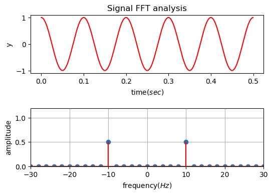
Figure 1. Result of FFT on a 10Hz signal
Let’s consider applying Fast Fourier Transform (FFT) to a 10Hz cosine function.
What result do we obtain? As shown at the bottom of Figure 1, do we get amplitudes of 10Hz and -10Hz frequencies that each take half of the total amplitude?
In other words, there are two key questions:
- Why negative frequencies? What is the physical meaning of negative frequencies?
- Why does the size become half?
The fundamental reason for these questions lies in the fact that we applied Fourier Transform to a real signal, and the key to the answer lies in the relationship between the Euler formula and harmonic waves.
Another way to represent $\cos\theta$ and $\sin\theta$
There are several ways to represent trigonometric functions, and one of the methods that signal processing practitioners should be familiar with is the representation of trigonometric functions using Euler’s formula.
Euler’s formula can be written as follows:
\[e^{i\theta} = \cos\theta + i \sin\theta\]Since $\cos$ and $\sin$ functions are even and odd functions, respectively, we can substitute $-\theta$ for $\theta$ in Equation (1) to obtain the following result:
\[e^{-i\theta}=\cos\theta - i\sin\theta\]By adding or subtracting Equation (1) and Equation (2), we can obtain new expressions for $\cos$ and $\sin$ functions as shown in the following two equations:
\[\cos(\theta) = \frac{e^{i\theta}+ e^{-i\theta}}{2}\] \[\sin(\theta) = \frac{e^{i\theta} - e^{-i\theta}}{2i}\]Here, the equation that we particularly want to focus on is Equation (3). If we examine Equation (3) in detail, it can be understood as follows.
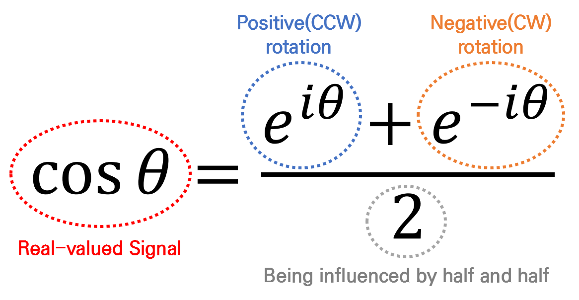
Figure 2. Another way to think about cosine function
In Figure 2, $\cos\theta$ is labeled as the real part of Equation (1), which is why $\cos\theta$ can also be seen as the real signal. In other words, by combining two complex space signals (i.e., vectors in the complex plane) that rotate in opposite directions, and taking half of their magnitudes, we can represent a real signal. This is consistent with what we observed in Figure 1 and the applet at the top of the document.