이 문서의 한국어 버전은 아래의 위치에서 찾을 수 있습니다. (You can find a Korean version of this article as below.)
0. prerequisites
To understand this post well, it is recommended to have knowledge of the following topics:
- Meaning of Imaginary Numbers
- Meaning of Natural Number e
- Derivation of Euler Equation and its meaning
1. What is a sinusoidal wave?
The statement that all signals that can be considered as the final conclusion of Fourier analysis can be expressed as a sum of sinusoidal waves is a statement that I heard with a sharp ear during my undergraduate years (if the reader is currently enrolled in an undergraduate program, they will hear it sharply too). This statement has a very important meaning, and among them, it provides a starting point for phasor analysis that enables signal analysis. That is, the unique analytical properties of sinusoidal waves provide a special signal analysis method called phasor analysis.
So what is a sinusoidal wave? It should not be forgotten that all sinusoidal waves are induced by the rotational motion of a bar. Let’s think about the rotational motion of the bar.
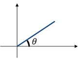
Figure 1. Bar with an angle of $\theta$ with the x-axis
Suppose we have a bar like Figure 1, tilted with an angle $\theta$ to the x-axis and centered on the origin. Let’s imagine that the bar rotates around the origin. The trajectory of the shadow reflected from top to bottom of the bar is called cosine. This is what we learned in middle school.
Then what is sine? We learned that sine is the trajectory of the shadow that appears when the light shines from right to left, but if we think about it, sine and cosine are just different starting points of the bar. In other words, when we rotate the bar by pulling it 90 degrees back, we can obtain the waveform of sine. This can be seen better in the right part of Figure 2.
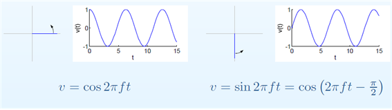
Figure 2. Cosine and sine waves are descriptions of the same "rotating circle" with only different starting points of the bar.
In other words, what we want to say here is that both sine and cosine can be thought of as cosine by reduction. The important premise of phasor analysis is to start from the assumption that all sinusoidal waves can be reduced to cosine. This is because it allows us to set the reference point of the phase. In other words, sine can be said to be like the trajectory of the shadow obtained by shining light from top to bottom when the angle of the bar is moved by $-\pi/2$ and the bar starts to rotate.
Now, let’s analyze the bar a little more mathematically.
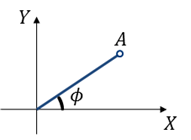
Figure 3. Bar with a length of $A$ and an angle of $\phi$ with the x-axis
As we can see in Figure 3, let the length of the rod be A and the initial angle at which it begins to rotate be $\phi$.
Assume that the rod rotates counterclockwise at a frequency of $f$ at this time. Then, if we represent the trajectory of the shadow obtained by shining light from top to bottom, we can express it as follows:
\[A \cos(2\pi f t + \phi)\] \[= A \cos(\phi) \cos(2\pi f t)-A \sin(\phi)\sin(2\pi f t)\] \[= X \cos(2\pi f t)- Y\sin(2\pi f t)\]In other words, assuming that the frequency component is fixed, we can decompose $A\cos(2\pi f t + \phi)$ using the cosine formula, as shown in (2), and obtain the coordinates of point A $(X,Y)=(A \cos (\phi) , A\sin(\phi))$, as seen in (3). The key idea of phasor analysis is that if the frequency component is fixed, it is sufficient to have the values of X and Y to represent the rotational motion of the rod with length A and initial angle $\phi$.
Therefore, we can consider the vector $(X,Y)=(A\cos(\phi), A\sin(\phi))$, and with just this two-dimensional vector, we can represent the rotational motion.
However, in phasor analysis, the coordinate system that represents this two-dimensional vector is assigned to the complex plane. The reason for this is that imaginary numbers represent rotation 1.
Therefore, the vector $(X,Y) = (A\cos(\phi), A\sin(\phi))$ can be expressed as follows:
\[(X,Y) = X+jY = A\cos(\phi) + jA\sin(\phi)\]Furthermore, we can also express it simply as the length and angle of the rod as follows.
\[A\angle\phi\]Therefore, by using four methods, it is possible to represent a rotating bar, and assuming the frequency is fixed, all four representation methods represent the same phenomenon. Among them, complex number notation and phasor notation are often used. Phasor refers to what is represented by a complex number notation or polar coordinate representation of a time function.
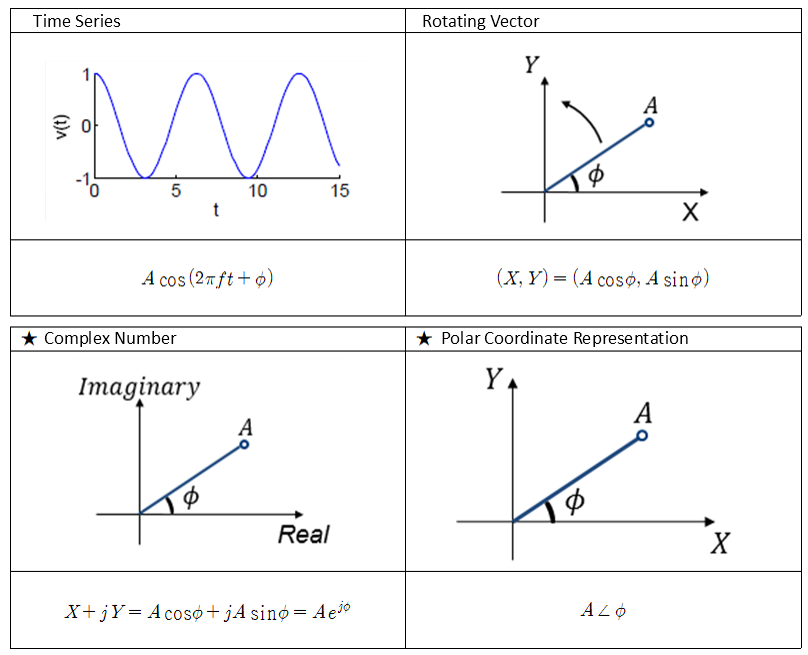
Figure 4. Four ways to represent a sinusoidal wave.
2. Examples of Phasors
Now that we have learned about the representation methods of phasors, let’s solve some simple examples. In all examples, we assume that the frequency is fixed. That is, $f$ is a constant.
Example 1) Express $v(t)=\cos(2\pi ft)$ in complex number notation and polar coordinate representation.
Answer: The complex number notation is $V=1$, and the polar coordinate representation is $1\angle 0°$.
Example 2) Express $v(t)=\sin(2\pi ft)$ in complex number notation and polar coordinate representation.
Answer: The complex number notation is $V=-j$, and the polar coordinate representation is $1\angle -90°$.
Example 3) Express $v(t)=-\cos(2\pi ft)+0.5\sin(2\pi ft)$ in complex number notation and polar coordinate representation.
Answer: The complex number notation is $V=-1-0.5j$, and the polar coordinate representation is $1.12\angle -153°$. Note that $V=X+jY$ is the same as $v(t)=X\cos(2\pi ft)-Y\sin(2\pi ft)$.
3. Operations and differentiation of phasors
Let’s compare some operations of rotating motion represented by phasors and time functions.
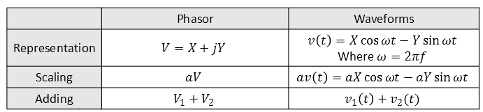
In other words, addition and scaling are the same in both phasors and waveforms. It is worth considering multiplication and division, but the most significant part of signal interpretation using phasors is calculus.
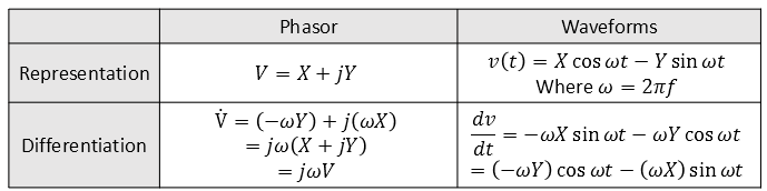
That is, using phasors, differentiating a waveform can be accomplished by simply multiplying by $j\omega$. This alone makes solving differential equations much easier.
Let’s emphasize once again that $\frac{d}{dt}v(t)$ and $j2\pi f\times V$ are equivalent. That is, simply multiplying $j2\pi f$ to the original phasor value can replace differentiation. Integration is the reverse, simply divide by $j2\pi f$. So why does multiplying by $j$ become equivalent to differentiation?
Returning to the beginning, every phasor is simply another representation of a sinusoidal wave. When we differentiate sine, it becomes cosine. Thinking of it as a bar, rotating sine into cosine is like rotating it by 90 degrees. Similarly, differentiating cosine gives -sine. Thinking of it as a bar, rotating cosine into -sine is like rotating it by 90 degrees.
That is, when we differentiate a sinusoidal wave, its overall shape (sinusoidal) remains unchanged and only the starting position of the rotation of the bar changes. Interestingly, when a sinusoidal wave is differentiated once, it changes into a form that rotates by 90 degrees as it changes position. As seen in “What is Imaginary?” post, imaginary numbers signify 90-degree rotations, so differentiation and rotation have equivalent meanings in sinusoidal waves. Therefore, if we can represent a sinusoidal wave as a complex number, multiplying it by $j2\pi f$ can signify differentiation.
4. RLC circuits and phasor
When interpreting RLC circuits, we learned that the relationship between the voltage and current of a capacitor and an inductor can be expressed by differentiation. For capacitors, this relationship is expressed by the formula:
\[i(t) = c {dv \over dt}\]When this is represented as a phasor, it becomes:
\[I = C \times j 2\pi f \times V\]or
\[V = I\times {1\over{j2\pi f C}}\]According to Ohm’s law, we know that $V=IR$, and the resistance of L and C is called reactance and is denoted by $X_L$ and $X_C$, respectively. Therefore, the reactance value for a capacitor is234:
\[X_C = {1\over {2\pi fC}}\]The impedance can be expressed as:
\[Z_C = {1\over {j2\pi fC}}\]For an inductor, the relationship between voltage and current is expressed by the formula
\[v(t) = L {di \over dt}\]which can be represented in phasor notation as
\[V = L\times j 2\pi f \times I\]Hence, the reactance is
\[X_L=2\pi fL\]and the impedance is
\[Z_L=j2\pi fL\]-
For those who do not understand that imaginary numbers mean rotation, please go to one of my previous blog articles Meaning of Imaginary Numbers ↩
-
Note that the capacitive reactance can sometimes be defined with a negative sign. For more information on this, please refer to the links in footnotes 4 and 5. The reason to put negative sign is because when you multiply “1/j” it beceomes “-j”. ↩
-
https://electronics.stackexchange.com/questions/203398/is-capacitor-reactance-sometimes-defined-with-negative-sign ↩
-
http://www.capacitorguide.com/impedance-and-reactance/ ↩